What is a Pipe Flange
A pipe flange functions as a joining mechanism to connect a system of pipes or tubing to various equipment and valves. Typically, two flanges are joined by bolts using a gasket between them for a seal leaving the opposite ends open for welding connections (Figure one). Flanges offer numerous advantages for joining pipe in highly corrosive or maintenance prone facilities. For instance, pipe systems that need to be regularly inspected or are prone to repair can be joined with flanges for quick disassembly. Flanged connections also allow for modifications to be made to the system without needing major fabrication.


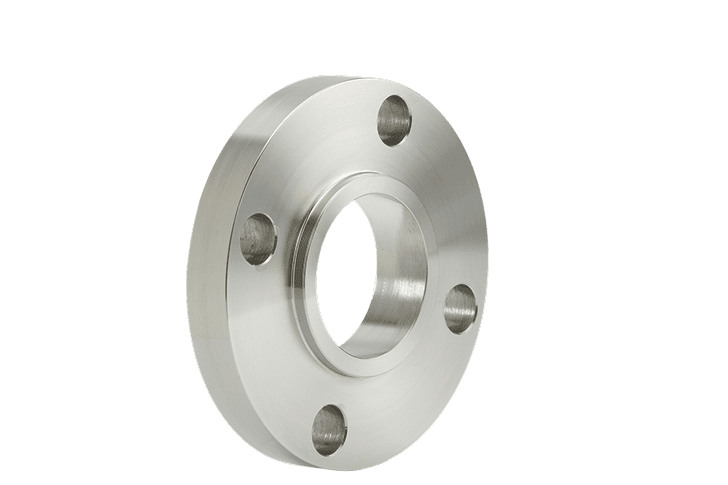
Weld Neck Flanges
- Preferred for high-pressure, subzero or elevated temperatures
- Hub is tapered and bored to match pipe’s inside diameter so flow is not restricted, preventing turbulence and reducing erosion
- Easily radiographed
- Provides excellent stress distributionThe Ladish name first enters the manufacturing market with a forging facility.
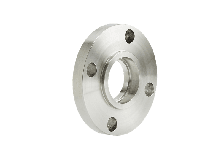
Slip-On Flanges
- Not normally used in high-stress applications due to low hub and weld attachment
- Slips over outside of pipe
- Inside of flange welded at hub and end of pipe

Blind Flanges
- Used to close ends of piping
- Has no bore
- Permits access to sealed lines
Socket Weld Flanges
- For small-diameter chemical processes, hydraulic and stream distribution lines
- Similar to slip-on flange
- Counter bore matches pipe bore, allowing unrestricted flow
- Counter bore from hub side fits pipe’s outer diameter – can insert pipe in socket with fillet weld at hub
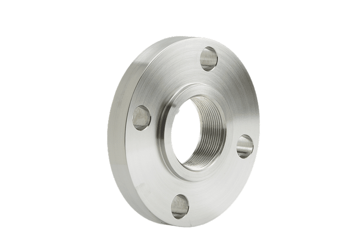
Threaded Flanges
- Used where welding would be hazardous
- Designed for low-pressure and non-cyclic applications
- Bore is threaded to match pipe thread
- Tapered to seal pipe and flange

Lap Joint Flanges
- Used where bolt alignment or access for cleaning is required
- Similar to slip-on flange when used with lap joint stub end
- Radius at intersection of flange face and bore to match lap joint stub end
Benefits of Using a Forged Flange
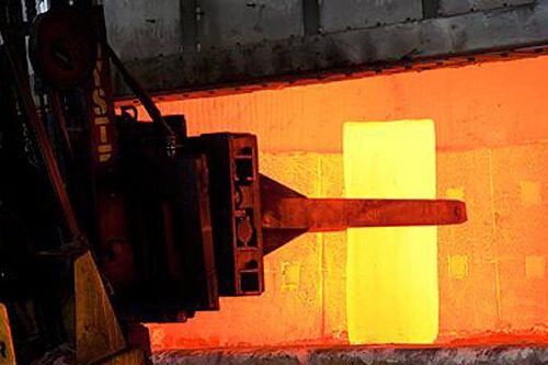
The process of open die forging has long been used to ensure strength, toughness, reliability, and the highest quality in flange manufacturing. Today, with greater demands being made in operating temperatures, loads, and stresses, the reliability of the metal and toughness has become increasingly critical. With the advancements of modern forging and machining, flanges in high grade alloys have excellent tolerance capabilities, superior corrosion resistance, and higher efficiency. Working the material at elevated temperatures achieves recrystallization and grain refinement, which results in greater metallurgical soundness and improved mechanical properties.
As seen in figure two, properly developed grain flow in forgings closely follows the outline of the flange. In contrast, bar stock and plate have unidirectional grain flow. Any changes in shape will cut the flow lines, exposing grain ends, and render the flange more susceptible to fatigue and corrosion. In addition, because forgings are designed to approximate final part shape, we can make better use of material than parts machined from bar stock or plate. Finally, forging eliminates internal gas pockets and voids in the material that could cause unexpected failure under stress or impact and further increases chemical uniformity throughout the flange.
Casting
No grain flow
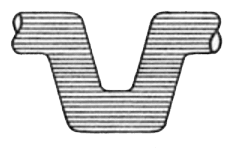
Bar Stock
Grain flow broken
by machining
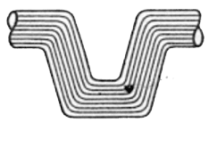
Forging
True grain flow
Rough Forged vs Rough Machined
Rough Forgings
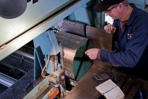
Western Forge & Flange offers rough forgings in a multitude of shapes and sizes for customers to machine into various parts and components outside of flanges. Every rough forging comes with a “machining allowance” or “forging envelope” which refers to the amount of stock left on the surface of the forging to be removed by subsequent machining. Depending on the material grade and size of the forging, the envelope will typically range from ½” to 2” (all over) of excess stock to protect the finishing dimensions provided by the customer. One of the main differences between rough forgings and rough machined forgings is that there is not an exact tolerance. As a manufacturer we cannot determine exactly how much overage there will be on the parts, although we try and get as close as possible to the finished dimensions.
Rough Machined Forgings
Often, the customer requests an initial machine pass to remove the top layer of flash or scale that forms during the forging process. Taking off the excess material helps create a more compatible surface (most notably the OD) for our customers equipment, and it gives us the ability to drill out the ID of a cylinder that would otherwise be forged solid. This reduces the customers manufacturing and machining time by reducing heavy cuts and simultaneously decreases transportation costs. When a rough machined forging is quoted there is an agreed upon tolerance between the manufacturer and the customer. This helps eliminate any of the unknown excess dimensions as stated above with the rough forgings. Rough Machined tolerances can be as lenient as ½” but can get as close as 1/32” on all dimensions.
Ready To Get Started?
Once you reach out to Western Forge & Flange, you’ll get the products you need in a hurry. Quick quotes and dependable delivery are part of our promise to you.